During lathe processing, the parts rotate continuously, and the processing efficiency is higher than that of other machine tools. However, for small parts and large quantities, the parts are repeatedly installed and removed on the chuck, the auxiliary time is long, and the relative efficiency decreases. In order to shorten the auxiliary time and improve the processing efficiency, the research and design installs the tool on the chuck and rotates continuously, and the parts only make feed motion.
Svart Hard Metal:
During lathe processing, the parts rotate continuously, and the processing efficiency is higher than that of other machine tools. However, for small parts and large quantities, the parts are repeatedly installed and removed on the chuck, the auxiliary time is long, and the relative efficiency decreases. In order to shorten the auxiliary time and improve the processing efficiency, the research and design installs the tool on the chuck and rotates continuously, and the parts only make feed motion. When replacing parts, the tool can continue to rotate, and the replacement of parts is simple and convenient, and the time is short.
A company processes a batch of hexagonal nut parts with specifications of M20, which need to be drilled and tapped. The method of installing the drill or tap on the chuck for cutting motion and installing the parts on the tool holder for feed motion has achieved good results.
Nut structure analysis and processing characteristics
The nut material is 45 steel, the blank is a cold forging blank, the inner hole has a 2mm machining allowance, and the outer hexagonal profile size is basically uniform and does not need to be processed. During processing, it is necessary to remove the 2mm allowance of the inner hole first, and then use a tap to tap the thread to complete. The process of processing nut threads on a lathe is to clamp a single nut on a three-jaw self-centering chuck, and then use a turning tool to process the inner hole and threads, or install a drill bit and a tap on the tailstock of a lathe, drill a hole with a drill bit, and use a tap to process threads. In both of the above methods, a single nut blank is installed on the chuck, the nut rotates, and the turning tool or drill bit (tap) performs a feed motion. The repeated operation is time-consuming and labor-intensive, and the processing efficiency is low. In order to increase the processing speed, it was decided to design a simple tooling, install the drill bit or tap on the three-jaw self-centering chuck for rotary motion, and install the nut to be processed on the tooling for feed motion, forming a processing mode.
Drilling method and design and use of tooling
According to the idea that the drill bit or tap rotates and the nut performs a feed motion, the drill bit or tap is installed on the three-jaw self-centering chuck, and a simple tooling is designed. The nut to be processed is installed in the tooling, and the tooling is installed on the tool holder, and the tool holder performs axial movement to realize the feed motion. The drilling method and tooling design are shown in Figure 1.
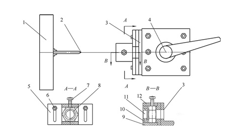
The tooling for installing nuts consists of a support bent plate 3, a connecting plate 5, a connecting bolt 6, a positioning bolt 7, a drill sleeve 11, an upper cover plate 12, a front end plate 10 and a bottom plate 9. The support bent plate 3 is installed on the lathe tool holder, and long holes are processed on both sides of the connecting plate 5, which is connected to the support bent plate by connecting bolts 6. Due to the existence of the long holes, the connecting plate can move up and down on the support bent plate to determine the processing position. The tightening bolt 7 is installed on the upper cover plate 12. After the processed nut is installed in the tooling, tighten the bolt to lock it. The drill sleeve 11 is installed in the front end plate to guide the drill bit or tap to ensure accurate processing. The drill sleeve is made of 45 steel and quenched to ensure wear resistance. The upper cover plate 12, the front end plate 10, the bottom plate 9 and the connecting plate 5 are welded together. Its width is equal to the maximum hexagonal size of the nut to be processed.
Before processing, first install the drill bit on the three-jaw self-centering chuck and lock it. Then install the support plate 3 on the lathe tool holder and lock it. Install the tooling on the support plate, level it, screw on the connecting bolts, and tighten them slightly.
For the first piece of processing, put the nut to be processed into the tooling from the side, preferably not exceeding the width of the tooling, tighten the fixing bolts 7 to fix the nut. Alignment. Move the connecting plate 5 up and down, move the slide in the tool holder perpendicular to the axis of the lathe, determine the position of the drill sleeve center and the lathe rotation center, and after confirming that the two coincide, tighten the connecting bolts 6, lock the slide, and the alignment is completed. At the beginning of processing, the spindle drives the drill bit to rotate, and the tool holder small slide moves forward axially. The drill bit starts drilling through the guide of the drill sleeve. After the drill bit passes through the hole on the connecting plate, it is determined that the drilling is completed. Move the tool holder small slide backward, the drill bit leaves the tooling, loosen the fixing bolts 7, put in the second nut from the side, and the first nut is squeezed out. Tighten the fixing bolts 7 again and lock the nut. Move the tool holder small slide, and the second processing begins. During the whole processing process, the drill bit keeps rotating, and only the tool holder moves axially. Since the alignment of the first piece has been completed, the subsequent processing does not require the alignment process, which greatly improves the processing efficiency.
Design of tapping tooling
When tapping internal threads, in order to prevent the occurrence of thread chaos due to the transmission error between the machine tool screw and the tap, a special tapping tooling chuck is designed, as shown in Figure 2.
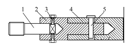
One end of the clamp 4 is installed on the three-jaw self-centering chuck, and the other end is installed in the inner hole. The drill sleeve is both the mounting sleeve of the drill sleeve and the guide sleeve of the drill sleeve. The two are matched with a small gap. A long hole is axially penetrated on the clamp to be used with the cylindrical pin 5. The drill sleeve is used to clamp the tap. The part is made of 45 steel and quenched. The cylindrical pin 5 and the drill sleeve are interference fit, which plays a role in driving the drill sleeve to rotate, and cooperates with the long hole on the clamp, which can make the drill sleeve have 4mm axial movement, which is used to eliminate transmission errors and prevent chaos. The set bolt 3 mainly serves to tighten the tap.
When processing the threaded sleeve, first remove the drill bit, install the threading tooling chuck on the three-jaw self-centering chuck, and lock it. The position of the tooling installed on the tool holder remains unchanged, and the nut to be tapped is sent into the tooling, and the set bolt 7 in Figure 1 is tightened to tap the thread. The spindle drives the tap to rotate, and the tool holder moves forward. After the cutting part of the tap passes through the nut, the spindle reverses and retracts, and the tool holder moves backward. The tapping of the first nut is completed. Then the second nut is sent in, and the first nut is squeezed out at the same time, and the above operation is repeated, and the cycle is completed.
Conclusion
The same lathe processing method uses simple tooling to change the installation position of the tool and the part, realizes the cutting movement of the tool and the feeding movement of the part, speeds up the cutting speed, simplifies the operation procedure, saves effort and time, and greatly improves the processing efficiency.


